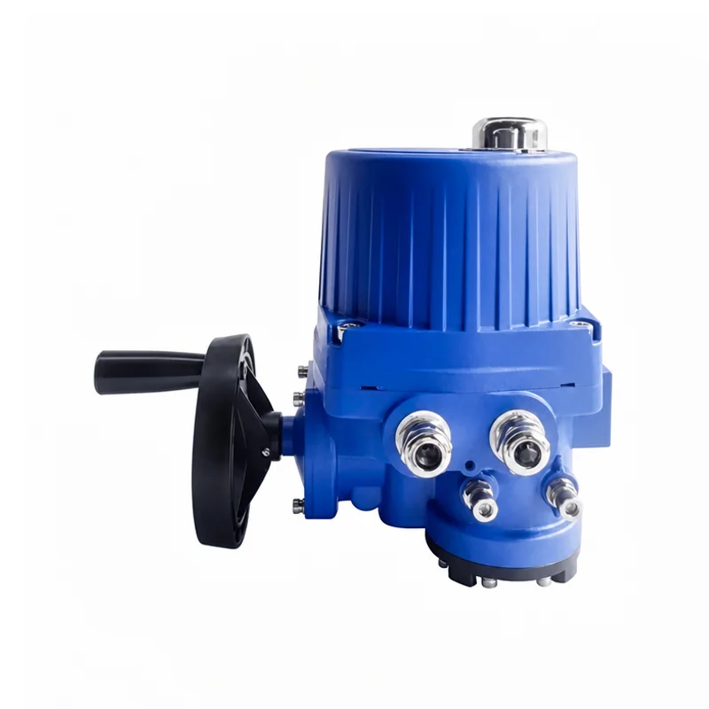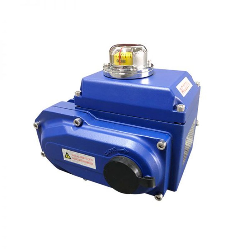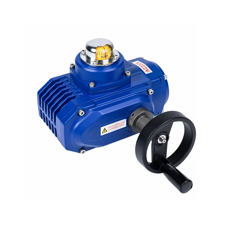

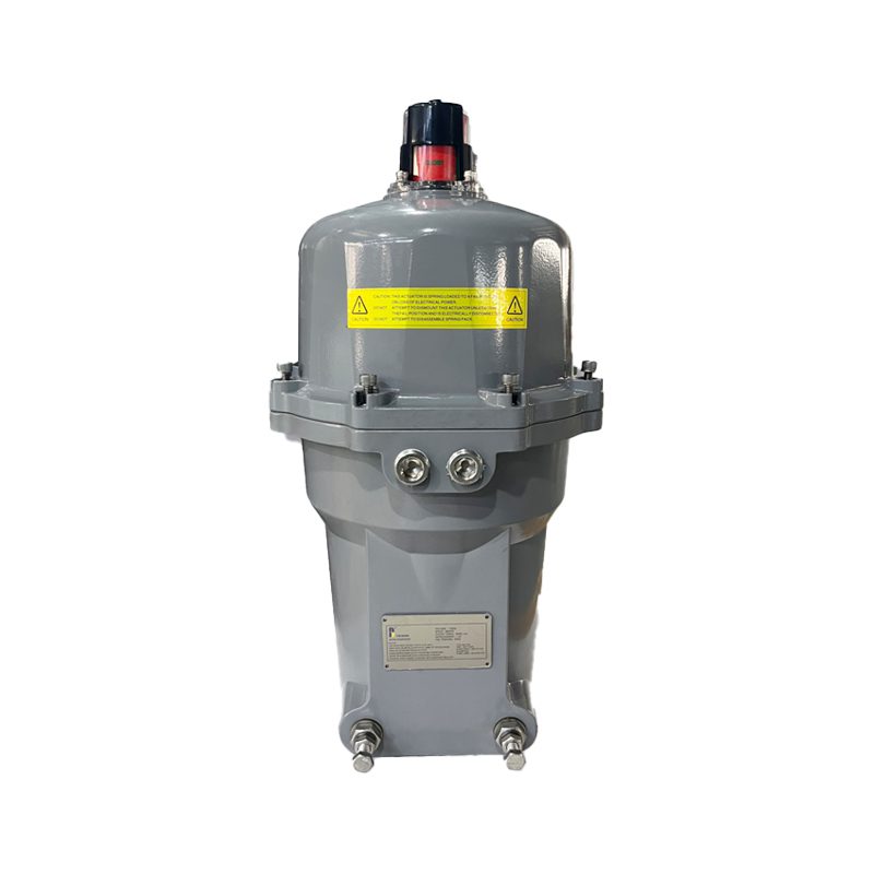
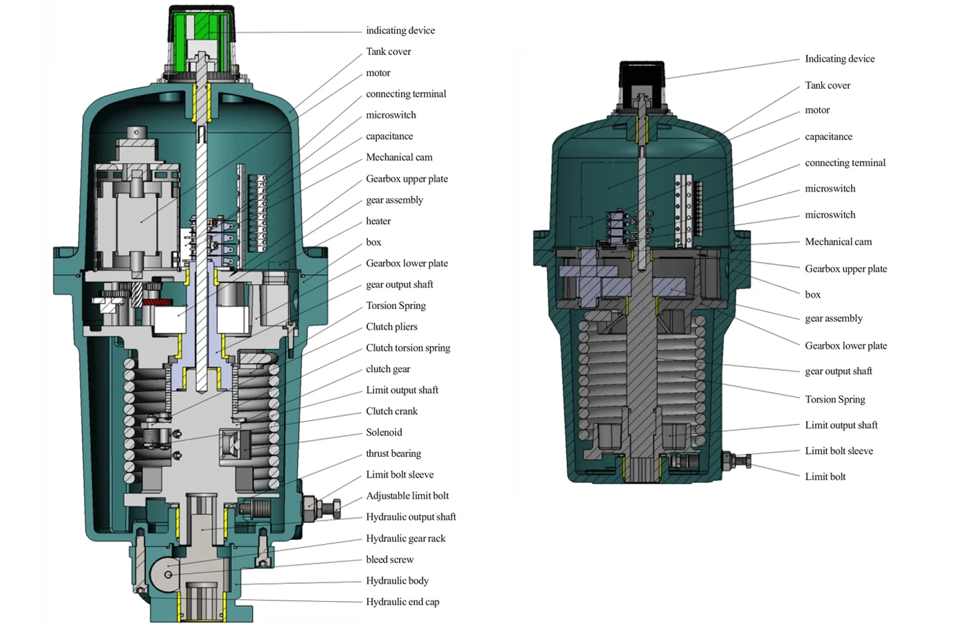
Standard Specifications
| Power Supply: | 24 VDC(BQSR-068 only) 120/220VAC 1PH,50/60 Hz |
|
| Motor | 24VDC | 24V 100W 5A(BQSR-068 only) |
| 110VAC | 110V, 50/60Hz, 30W, 0.5A | |
| 220VAC | 220V,50/60Hz, 30W,0.33A | |
| Limit Switches |
24VDC | 15A 1/2HP @125/250VAC(BQSR-068 only) |
| 11OVAC | 11A 1/3HP @125/250/277VAC 1/2A 125VAC, 1 1/4A 250VAC |
|
| 220VAC | 11A 1/3HP @125/250/277VAC 1/2A 125VAC, 11/4A 250VAC |
|
| Stall Protection: | Built in thermal protection,Open at 130±5°C,Close at 85±15°C | |
| Travel Angle: | 0 to 90°±10° | |
| Indicator: | Continuous position indicator | |
| Space Heater: | 10W 2.5A Anti-Condensation | |
| Cable Conduit: | Two 3/4″ NPT (BQSR-034 has One 3/4″ NPT) | |
| Lubrication: | Grease Synthetic | |
| Terminal Block: | Spring loaded lever push type | |
| Materials: | Carbon Steel, Alloy Steel, Spring Steel,Stainless Steel, Aluminum Alloy, NBR,ABS and Polycarbonate Plastic |
|
| Ambient Temperature: | -40°F to 140°F(-40°C to 60°C) | |
| Bxternal Coating: | Powder Coating | |
Technical and Dimensional Infomation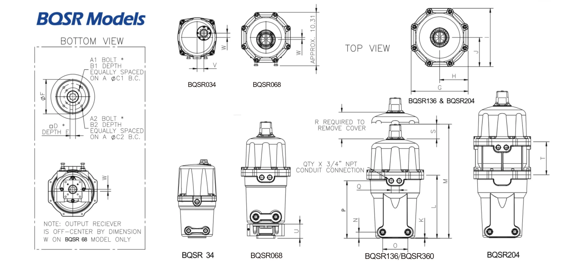
Dimensions(mm)
| Model | IS05211 | A1 | A2 | B1 | B2 | C1 | C2 | D | AND | F | G | H | I | J |
| BQSR034 | F07 | 5/16-18 | – | 12 | – | 70 | – | 17 | 29 | 96 | 195 | 97.5 | 202.4 | 105 |
| BQSR068 | FO7/F10 | 5/16-18 | 3/8-16 | 15 | 15 | 70 | 102 | 19 | 48 | – | 246 | 123 | 245 | 123 |
| BQSR136 | F07/F10 | 5/16-18 | 3/8-16 | 12 | 15 | 70 | 102 | 22 | 31 | 135.6 | 286 | 143 | 286 | 143 |
| BQSR204 | F07/F10 | 5/16-18 | 3/8-16 | 12 | 15 | 70 | 102 | 22 | 31 | 135.6 | 286 | 143 | 286 | 143 |
| BQSR360 | F10/F12 | 3/8-16 | 1/2-13 | 18.8 | 22.6 | 102 | 105 | 27 | 43.7 | 155.7 | 357 | 178.6 | 357 | 178.6 |
| Model | K | L | M | N | THE | P | Q | R | S | T | IN | In | IN | X |
| BQSR034 | 7 | 195 | 383 | 35 | 85 | 195 | – | 148.6 | 22 | – | – | 34 | 21 | 25.4 |
| BQSR068 | 5 | 322 | 572 | 105 | 100 | 298.5 | 40 | 136.4 | 72 | – | 70 | – | 10 | 50.8 |
| BQSR136 | 2 | 309 | 559 | 30 | 126 | 309 | 40 | 138 | 72 | – | – | – | – | 50.8 |
| BQSR204 | 2 | 309 | 721 | 30 | 126 | 443.5 | 40 | 139 | 72 | 162 | – | – | – | 50.8 |
| BQSR360 | 2 | 466 | 766 | 40 | 160 | 436 | 50 | 180 | 72 | – | – | – | – | 50.8 |
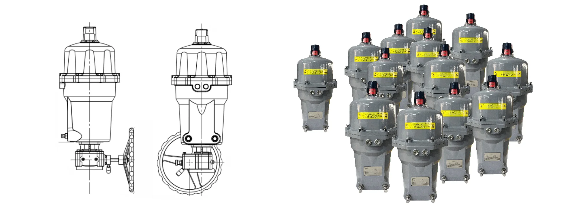
Bqsr With 2rdgo
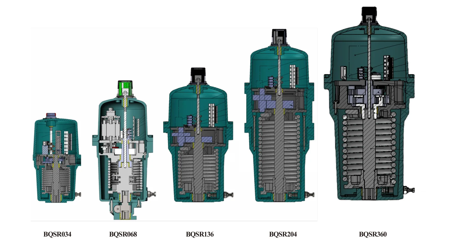
Wiring Diagram Reference
| Model | Description | Drawing |
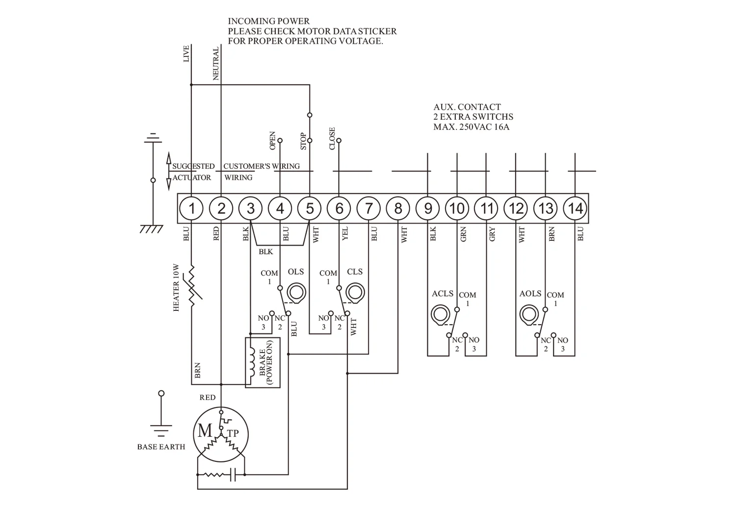
| BQSR034thru BQSR360 | 115/220 VAC 1PH, Two Position | SE01668 |
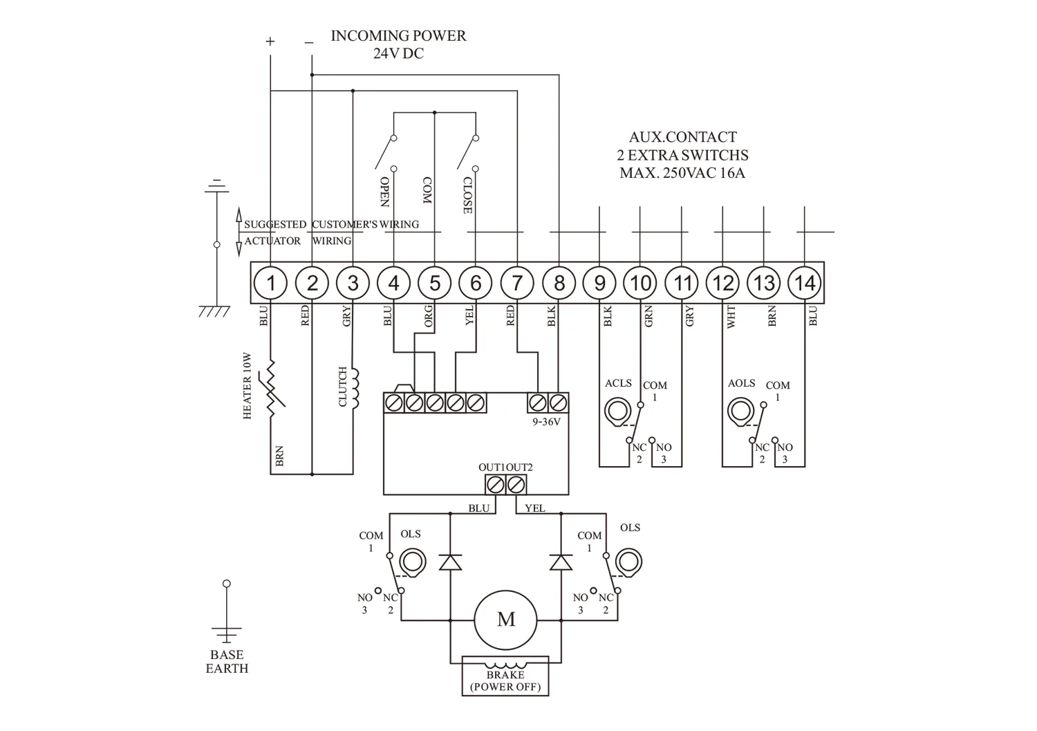
| BQSR068 | 24 VDC | SE01669 |
Technical Data
| Actuator Model |
Spring EndTorque |
90Cycle Time |
SpringFail Time |
Motor Size |
Rated Amps | Duty Cycle |
Weight | |||
| DC | AC | Standard | w/Manua Override | |||||||
| SIZE | N-m | seconds | seconds | Watts | 24V | 110V | 220V | % | KGs. | KGs. |
| BQSR034 | 34 | 10 | 4 | 30 | N/A | 1 | 0.5 | 50 | 14.4 | 32.4 |
| BQSR068 | 68 | 30 | 2 | 30 | 2 | 1 | 0.5 | 50 | 27.9 | 45.9 |
| BQSR136 | 136 | 30 | 7 | 30 | N/A | 1 | 0.5 | 50 | 36 | 54 |
| BQSR204 | 204 | 30 | 7 | 30 | N/A | 1 | 0.5 | 50 | 54 | 72 |
| BQSR360 | 360 | 30 | 4 | 80 | 5 | 1.4 | 0.7 | 50 | 96.8 | 126.5 |
BE01669
| LIMIT SWITCH OPERATION | |||
| SWITCH | CLOSE←INTERMEDIATE→OPEN | ||
| CLS 1-2 | ---- | ---- | |
| CLS 1-3 | ---- | ||
| OLS 1-2 | ---- | ---- | ---- |
| OLS 1-3 | ---- | ||
| ACLS 1-2 | ---- | ---- | |
| ACLS 1-3 | ---- | ||
| AOLS 1-2 | ---- | ---- | |
| AOLS 1-3 | ---- | ||
| SYMBOL | DESCRIPTION | RATING | |
| ACLS | AUX.CLOSE LIMIT SWITCH (TOP) | 250VAC 15A | |
| CLS | CLOSE LIMIT SWITCH | 250VAC 15A | |
| AOLS | AUX.OPEN LIMIT SWITCH | 250VAC 15A | |
| OLS | OPEN LIMIT SWITCH (BOT) | 250VAC 15A | |
| *EACH ACTUATOR SHOULD BE POWERED THROUGH IT’S OWN INDIVIDAL SWITCH OR RELAY CONTACTS TO PREVENT CROS SFEED BETWEEN TWO OR MORE ACTUATORS. |
|||
Operation Notes:
1.Power to terminal 2 & 4 will drive motor CCW.Brake energizes when NO of OLS closes to hold actuator in CCW position.
2.Power to terminal 2 & 6 will drive motor CW.Brake energizes when NO of CLS closes to hold actuator in CW position.
3.Power to terminal 2 & 5 will energize brake and hold actuator in intermediate STOP position.
4.Loss of power will release spring clutch and return actuator to fail position (limited by adjustable stop).
BE01668
| LIMIT SWITCH OPERATION | |||
| SWITCH | CLOSE←INTERMEDIATE→OPEN | ||
| CLS 1-2 | ---- | ---- | |
| CLS 1-3 | ---- | ||
| OLS 1-2 | ---- | ---- | ---- |
| OLS 1-3 | ---- | ||
| ACLS 1-2 | ---- | ---- | |
| ACLS 1-3 | ---- | ||
| AOLS 1-2 | ---- | ---- | |
| AOLS 1-3 | ---- | ||
| SYMBOL | DESCRIPTION | RATING | |
| ACLS | AUX.CLOSE LIMIT SWITCH (TOP) | 250VAC 15A | |
| CLS | CLOSE LIMIT SWITCH | 250VAC 15A | |
| AOLS | AUX.OPEN LIMIT SWITCH | 250VAC 15A | |
| OLS | OPEN LIMIT SWITCH (BOT) | 250VAC 15A | |
| *EACH ACTUATOR SHOULD BE POWERED THROUGH IT’S OWN INDIVIDAL SWITCH OR RELAY CONTACTS TO PREVENT CROS SFEED BETWEEN TWO OR MORE ACTUATORS. |
|||
Operation Notes:
1.Power to terminal 2 & 4 will drive motor CCW.Brake energizes when NO of OLS closes to hold actuator in CCW position.
2.Power to terminal 2 & 6 will drive motor CW.Brake energizes when NO of CLS closes to hold actuator in CW position.
3.Power to terminal 2 & 5 will energize brake and hold actuator in intermediate STOP position.
4.Loss of supply power will release brake and return actuator to fail position (limited by odjustable stop).
Confirm the Right BQSR Series Spring Return Electric Actuator
Send the valve type, size and torque, the air supply or voltage, and whether it should fail open, fail close or stay in place. The quotation is confirmed against that duty.